
Why rooftop plant changes the noise risk for data centres
Putting heat rejection plant on the roof is usually a sound decision. It frees ground level area for electrical infrastructure and access, it shortens pipe runs, it keeps plant away from vehicle movements, and on constrained urban sites it may be the only place the equipment fits. It also changes the acoustic problem in ways…
Putting heat rejection plant on the roof is usually a sound decision. It frees ground level area for electrical infrastructure and access, it shortens pipe runs, it keeps plant away from vehicle movements, and on constrained urban sites it may be the only place the equipment fits.
It also changes the acoustic problem in ways that are frequently not recognised until a noise model comes back over the criterion. Rooftop plant is not inherently non-compliant. What it does is remove several forms of attenuation that ground level plant receives at no cost, and it narrows the set of mitigation options available once the arrangement is fixed.
For anyone assessing a proposed rooftop layout or reviewing a consultant’s model, the questions below are the ones that separate a sound assessment from an optimistic one.
Elevation removes the building as a barrier
Ground level plant located behind a building is screened by that building. The structure is large, solid and sits directly in the propagation path, which produces the most reliable attenuation available on any site.
Move the same plant to the roof and the building stops being a barrier. It becomes a plinth that raises the source above the surrounding terrain and into direct line of sight with receivers that were previously shielded. Nothing about the equipment has changed. The path has.
This is the first thing to check in a rooftop assessment. Which receivers now have unobstructed line of sight to the plant that would not have had it at ground level, and has the model been rerun for those receivers rather than for the ones identified at concept stage.
Ground attenuation largely disappears
Outdoor propagation calculations to ISO 9613-2 include a ground attenuation term that depends on the height of the source, the height of the receiver and the ground between them. Soft ground under a low source and a low receiver produces useful attenuation, particularly in the mid frequencies.
Raise the source thirty metres and that mechanism weakens substantially. The propagation path spends most of its length well above the ground, so the ground has less opportunity to influence it. An assessment that carries forward ground attenuation values derived for a ground mounted arrangement will understate the result.
There is a related trap in how barriers and ground effect combine. As set out in analysis of barrier handling in ISO 9613-2, the screening term in the standard already contains the ground attenuation, and the two ground terms cancel when combined. Barrier attenuation and ground attenuation are not additive, and a model that treats them as though they are will produce a number that cannot be achieved.
Barrier attenuation has a ceiling, and low frequencies never reach it
Rooftop screens are the standard response to rooftop plant, and they work. They do not work as well as the arithmetic in a specification sometimes assumes.
ISO 9613-2:2024 limits calculated screening attenuation to 20dB for a single screen and 25dB where multiple screens are involved. Those are the ceilings for the method, regardless of how tall the screen is drawn, and they are unchanged from the 1996 edition.
Well below those ceilings, the frequency dependence governs. Diffraction attenuation is set by the Fresnel number, which is proportional to the path difference divided by the wavelength. A screen that adds 0.3m of path difference produces a Fresnel number of about 3.5 at 2 kHz, where it screens well, and about 0.11 at 63 Hz, where it does almost nothing.
|
Frequency |
Wavelength |
Fresnel number for 0.3m path difference |
|
63 Hz |
5.44m |
0.11 |
|
125 Hz |
2.74m |
0.22 |
|
250 Hz |
1.37m |
0.44 |
|
500 Hz |
0.69m |
0.87 |
|
1 kHz |
0.34m |
1.75 |
|
2 kHz |
0.17m |
3.50 |
The practical consequence is that a screen sized against an overall dB(A) target may deliver most of that reduction in bands that were never the problem. Where the governing content is fan blade passage energy in the 63 Hz to 125 Hz region, screening alone will not resolve it, and the assessment should show octave band results rather than a single figure. Low frequency content is exactly the case examined in designing attenuation for performance below 125 Hz.
Receiver height decides whether the screen works at all
A screen only produces attenuation where it interrupts the line between source and receiver. For a rooftop source, whether that happens depends on the height of the receiver as much as the height of the screen.
An assessment carried out at ground floor level at a nearby residential building may show comfortable compliance while the third floor of the same building looks straight over the parapet at the condenser deck. Where receivers are multi storey, the assessment locations should reflect the most exposed habitable position, not the most convenient one.
The same logic applies over time. A screen sized against today’s receivers may be defeated by a taller building approved next door in five years. That is not a reason to oversize a screen. It is a reason to state the assumption explicitly in the assessment so that the limitation is visible.
The screen that fixes the noise can degrade the cooling
This is the trade off that most often forces a redesign, and it is the strongest argument for treating rooftop acoustics and rooftop mechanical design as one exercise.
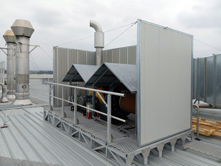
Air cooled heat rejection plant needs unobstructed intake and a clear discharge path. A solid screen close to the equipment does three things at once. It restricts the intake path, raising static pressure. It obstructs the discharge, which can allow warm discharge air to return to the intake. And in a fully screened deck, it forms a partially enclosed volume where the air is warmer than ambient.
Every one of those effects raises the condensing temperature, and the control response is to increase fan speed. ASHRAE gives the change in fan sound power as approximately 50 times the logarithm of the speed ratio.
|
Increase in fan speed |
Increase in fan sound power level |
|
5 per cent |
1.1dB |
|
10 per cent |
2.1dB |
|
15 per cent |
3.0dB |
|
20 per cent |
4.0dB |
|
25 per cent |
4.8dB |
A screen that costs the plant 15 per cent in fan speed has given back about 3dB of source level before any acoustic benefit is counted. It has also reduced available cooling capacity on exactly the hot days when the facility needs it most.
This is why rooftop screening should be verified against airflow as well as acoustics. Integrating CFD and acoustic modelling for plant design exists precisely because the two analyses answer questions that the other one creates.
There is a second effect inside a screened deck. Screens on several sides create a partially reverberant space, which raises the sound pressure level at the plant and at the top of the screen. Absorptive treatment on the inner face of the screen addresses this. A purely reflective screen does not.
Structure sets the limit on screen height
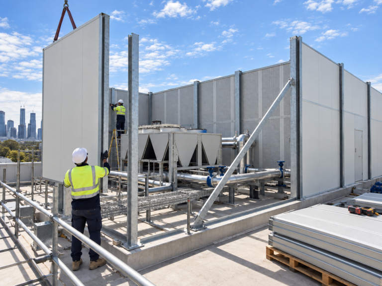
Rooftop screens attract wind actions, and those actions increase with height above ground. On a roof, they have to be resolved into a structure that was designed for a plant load case, not a sail.
Barrier and screen walls built from Sonic System acoustic modular panels carry published wind load capacities that vary with support spacing. The V50 panel is rated up to 6.0 kPa at 0.9m to 1.5m support centres, reducing to 1.9 kPa at 2.7m centres, and the V100 panel up to 2.58 kPa at 4.0m centres reducing to 1.15 kPa at 6.0m. The published values are noted as not applicable to cyclonic wind regions.
The point for an assessor is that screen height is not a free variable. Where a model relies on an additional metre of screen to achieve compliance, the structural implication of that metre should be confirmed before the result is relied on.
Where the options narrow
Once a rooftop arrangement is fixed, the mitigation set is smaller than it looks.
Relocation is usually unavailable, because the plant deck is the only place the equipment fits. Screen height is bounded by structure and wind. Screen proximity is bounded by airflow. Enclosure is bounded by heat rejection. Quieter equipment is available but has a longer lead time and often a larger footprint, which the deck may not have.
What remains are the treatments that work with airflow rather than against it. Attenuated discharge and intake paths using Sonic acoustic attenuators where the plant is ducted. Screens incorporating Sonic Series acoustic louvres so that air passes through an attenuated opening rather than being forced over the top, with published free area between 21 and 35 per cent across the models with published datasheets. Absorptive inner faces using Sonic System acoustic modular panels, published with a perforated face at up to 38 per cent open area and NRC values up to 1.10 for the V100, to control build up within the deck.
All of these are easier to accommodate when the deck layout is still being drawn.
What to interrogate in a rooftop assessment
Elevation and geometry, not equipment selection, are what make rooftop plant a different acoustic problem. An assessment that reflects that will show several things a generic one will not.
Receiver locations that include upper storeys, chosen after the plant moved to the roof rather than before. Ground attenuation values consistent with an elevated source. Barrier and ground terms combined as the standard requires rather than added. Octave band results, so it is visible which bands the screening actually treats. A stated screen height with a structural basis. And confirmation that the screening arrangement has been checked against intake and discharge airflow, with the fan operating point that the assessment assumes.
If those six things are present, the assessment can be relied on. If they are not, the number may be correct for a building that will not be built.
Related Stories
-
When an acoustic louvre is the right choice and when it is not
An acoustic louvre is asked to do three incompatible things through the same aperture. It has to let air through, keep water out, and attenuate sound. Each of those improves at the expense of the… -
Insertion loss, transmission loss and Rw, choosing the right metric for the job
A mechanical engineer sizing a duct attenuator, an architect specifying a plantroom wall and a project manager reviewing a supplier submission can all be looking at a number followed by the letters dB and be… -
The acoustic specification brief, what consultants need from suppliers at tender stage
Three suppliers return prices against the same acoustic scope. The spread is forty per cent. Procurement reads that as a commercial finding, asks the lowest bidder to confirm compliance, receives a one line confirmation, and…