
Insertion loss, transmission loss and Rw, choosing the right metric for the job
A mechanical engineer sizing a duct attenuator, an architect specifying a plantroom wall and a project manager reviewing a supplier submission can all be looking at a number followed by the letters dB and be looking at three different physical quantities. The three that cause the most trouble on industrial and building services projects are…
A mechanical engineer sizing a duct attenuator, an architect specifying a plantroom wall and a project manager reviewing a supplier submission can all be looking at a number followed by the letters dB and be looking at three different physical quantities.
The three that cause the most trouble on industrial and building services projects are insertion loss, transmission loss and the weighted sound reduction index, Rw. They are related, they share units, and they are routinely substituted for one another in tender documentation. They are not interchangeable, and the substitution has consequences that show up as a compliance shortfall rather than as an obvious error.
The distinction is not academic pedantry. Each quantity is produced by a specific test arrangement, and each arrangement was built to answer a specific question. Using the answer to one question as the answer to another is where the design margin quietly disappears.
Transmission loss describes a partition
Transmission loss, or sound reduction index R, is the ratio of the sound power incident on an element to the sound power transmitted through it, expressed in decibels. It is a property of the element itself.
Measuring it requires a laboratory suite of two reverberant rooms separated by a test aperture, with the element mounted in that aperture and flanking transmission suppressed. In Australia the relevant method is AS 1191-2002, Acoustics, Method for laboratory measurement of airborne sound transmission insulation of building elements. Internationally the equivalent sits in the ISO 10140 series.
The result is a set of values in one third octave bands. It describes how the element behaves when sound arrives at it from a diffuse field on one side and radiates into a diffuse field on the other. That is a good model of a wall between two rooms. It is a much weaker model of a component sitting in a duct with air moving through it, or of a louvre in the wall of an outdoor enclosure radiating to a free field.
RW is a rating of that data, not a separate measurement
Rw is not a measurement. It is a single number derived from third octave transmission loss data by the curve fitting procedure in ISO 717-1, rated to AS/NZS ISO 717.1 in Australian documentation.
Two properties of that procedure matter in practice.
The first is the frequency range. The rating is derived from data between 100 Hz and 3150 Hz. Below 100 Hz the rating carries no information at all. For a partition separating occupied rooms, that range is reasonable. For an enclosure around a diesel generator, a large centrifugal fan, a transformer or a reciprocating compressor, a large part of the acoustic energy sits at 63 Hz and below, entirely outside the range the rating describes.
The second is the reference curve. The fitting procedure weights the data against a standard shape. Two elements with the same Rw can have different transmission loss curves, and can differ by several decibels in the octave band that governs a particular project. This is why ISO 717-1 also defines the spectrum adaptation terms C and Ctr, which shift the rating toward a pink noise spectrum and toward a traffic type low frequency spectrum respectively. We publish our Sonic System acoustic modular panel ratings with those terms alongside the single figure in the technical data, which tells a reader considerably more about the 100mm V100 at Rw 37dB than the single figure does on its own.
Insertion loss describes a change to an installation
Insertion loss is the difference in sound level at a defined position, or in radiated sound power, with and without the component installed, everything else held constant. It is a property of the component in a configuration, not of the component alone.
For ducted attenuators the laboratory procedure is ISO 7235, Acoustics, Laboratory measurement procedures for ducted silencers and air-terminal units, which produces insertion loss, flow noise and total pressure loss together. Producing them together is the point. An attenuator changes three things at once, and its acoustic result cannot be separated from the flow condition it is operating in.
ISO 14163 sets out the relationship. Under laboratory conditions with a well controlled termination, the insertion loss and the transmission loss of a silencer converge. In a real installation they do not, because end reflections, duct breakout, the impedance the silencer sees at each end, and the uniformity of the approach flow all differ from the laboratory arrangement. The standard also defines regenerated sound as flow noise caused by the flow conditions in the silencer, and notes that performance is affected when the inlet flow distribution departs from the uniform laboratory case.
That is why insertion loss quoted without a flow rate, and without a direction of flow relative to the direction of sound propagation, is an incomplete figure.
The metric follows the question
|
Engineering question |
Quantity that answers it |
Typical test arrangement |
|
How much sound passes through this wall or door |
Transmission loss in bands, Rw as a summary |
Two room laboratory suite, AS 1191-2002, rated to AS/NZS ISO 717.1 |
|
How much quieter is the duct outlet once this attenuator is fitted |
Insertion loss in octave bands at the design flow |
Duct rig with flow, ISO 7235 |
|
How much does this enclosure reduce the radiated sound power of the plant inside it |
Insertion loss of the assembly |
In situ or calculated, not the panel rating |
|
How much noise reaches this receiver |
Sound pressure level, after propagation modelling |
Field measurement or prediction from sound power |
|
What is the strength of the source |
Sound power level in bands |
ISO 3744 engineering grade, ISO 3746 survey grade |
Two errors recur often enough to be worth naming.
The first is treating an enclosure panel rating as an enclosure performance. The second is comparing a sound power level to a sound pressure criterion. Sound power is a property of the source and does not vary with distance or surroundings. Sound pressure depends on distance, directivity, ground, screening and meteorology. A generator quoted at a sound power level of 105dB(A) and a boundary criterion of 45dB(A) are not two numbers that can be subtracted.
It is also worth separating dB from dB(A). A weighted level applies a frequency weighting intended to approximate human hearing sensitivity at moderate levels, and it deliberately discards low frequency content. Attenuation requirements derived only from A-weighted arithmetic will systematically understate what is needed at 63 Hz and 125 Hz.
Why an Rw 45 panel does not produce a 45dB enclosure
The most expensive version of the metric error is the enclosure that is designed from its panel rating.
Consider a plant enclosure with 100 m2 of wall built from a panel rated Rw 45dB, and 1 m2 of unattenuated opening, whether that is a ventilation aperture, an unsealed service penetration or the sum of gaps around a poorly fitted door.
Composite transmission loss is calculated by area weighting the transmission coefficients, not the decibels. A panel at 45 dB has a transmission coefficient of about 3.2 x 10⁻⁵. The open area has a transmission coefficient of 1.
The area weighted mean is (99 x 3.2 x 10-5 + 1 x 1) / 100, which is approximately 0.0100, and the composite result is about 20 dB.
One per cent open area caps a 45 dB wall at roughly 20 dB. The enclosure has lost 25 dB of its notional performance to a hole.
Two qualifications belong with that arithmetic. It is a band by band calculation properly done with transmission loss data rather than with a single number rating, and the worked figure above uses the rating only to illustrate the mechanism. It also ignores internal reverberant build up inside the enclosure, which raises the sound pressure incident on the walls and reduces the achieved insertion loss further unless absorptive linings are provided. Our Sonic System acoustic modular panels carry published NRC values alongside their Rw values for that reason. The insulating face and the absorbing face are doing two different jobs.
The engineering conclusion is that an enclosure is assessed on its insertion loss, and its insertion loss is governed by its weakest paths, which are almost always the openings the plant needs in order to run.
Louvres, and the honesty of the evidence class
Acoustic louvres sit awkwardly between the two families, which is why they attract more metric confusion than any other component.
They are usually rated as building elements. We publish our Sonic Series acoustic louvres with Rw values, from Rw 18dB for the 100mm SL4-10 to Rw 33dB for the 600mm SL4-60. This range is published assessed to AS 1191-2002 and rated to AS/NZS ISO 717.1, with full performance data available on request.
Both facts are useful to a specifier, and both should be read for what they are. The rating is a partition style rating applied to a component whose real job is to attenuate sound passing through an opening while passing air through the same opening. The engineering question at the boundary is usually closer to “how much sound power leaves this aperture” than “what is the sound reduction index of this element”, and the answer to that depends on the aperture area, the sound field behind it and the directivity of the opening, not only on the rating of the louvre.
None of that makes the published rating wrong. It makes it one input rather than the answer.
The three quantities are not competing descriptions of the same thing. Transmission loss describes an element. Rw summarises transmission loss data over a defined frequency range using a defined curve. Insertion loss describes what changes when a component is placed into a particular installation under particular operating conditions.
The practical discipline is to write the engineering question first and select the metric second. If the question involves airflow, the answer is almost certainly insertion loss at a stated flow. If it involves a partition between two spaces, it is transmission loss, with Rw as shorthand and octave band data as the real working input. If it involves an enclosure, it is the insertion loss of the assembly including every opening, and no panel rating will substitute for it.
Where a single number is all that is available, the correct response is not to reject it but to ask what it was derived from, over what frequency range, under what test arrangement and with what class of evidence behind it.
Related Stories
-
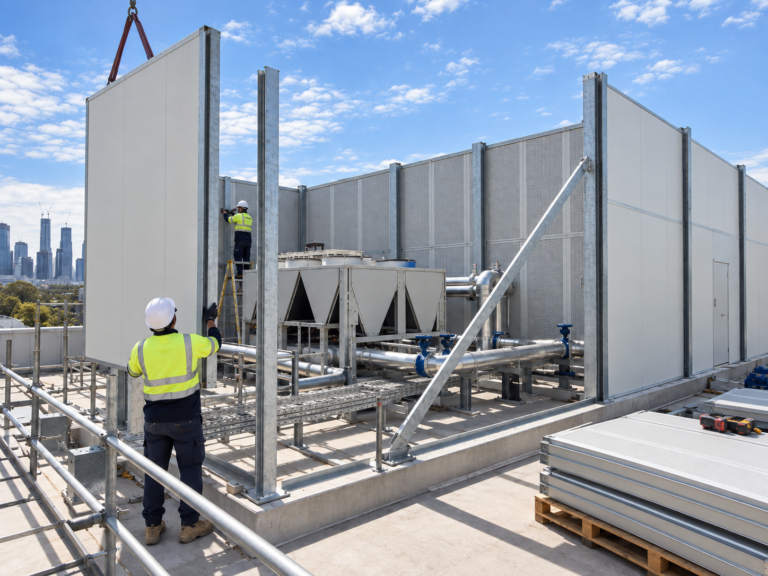
The acoustic specification brief, what consultants need from suppliers at tender stage
Three suppliers return prices against the same acoustic scope. The spread is forty per cent. Procurement reads that as a commercial finding, asks the lowest bidder to confirm compliance, receives a one line confirmation, and… -
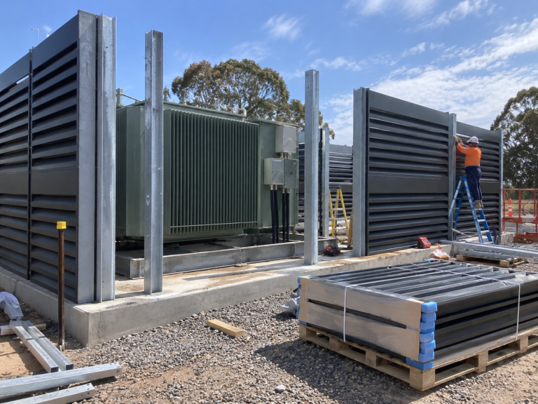
Tonal noise in BESS, why a compliant dB(A) figure may not tell the whole story
An overall A-weighted level answers one question. How much acoustic energy arrives at the receiver, weighted roughly for the sensitivity of human hearing. It does not answer the question residents near battery energy storage sites… -
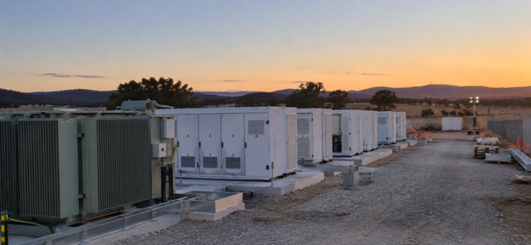
Designing BESS sites for social licence, what noise planning can contribute
In August 2026 the ABC reported on community concern about a proposed 520 megawatt battery energy storage facility at Uriarra Station in the Australian Capital Territory, around two kilometres from Uriarra Village and roughly 30…