
Designing generator intake and discharge paths without creating an acoustic weak point
A generator enclosure is an unusual acoustic object. Almost every other enclosure on a project is trying to be closed. This one has to move an enormous volume of air through itself continuously while the machine inside is running, and the volume is set by the engine, not by the acoustic design. That is the…
A generator enclosure is an unusual acoustic object. Almost every other enclosure on a project is trying to be closed. This one has to move an enormous volume of air through itself continuously while the machine inside is running, and the volume is set by the engine, not by the acoustic design.
That is the whole planning problem. The enclosure walls are the easy part. The openings that make the machine survivable are where the acoustic performance is decided, and they are governed by constraints that belong to the engine manufacturer rather than to the acoustic consultant.
On data centre projects this arrives with two additional pressures. The generator plant is usually sized with redundancy, so there are several sets rather than one, and the site is frequently at the edge of an industrial zone with residential receivers within a few hundred metres.
Four paths, not one
A radiator cooled generator set has four separate paths through the enclosure boundary, and each behaves differently.
Combustion air is drawn in to feed the engine. The volume is comparatively modest.
Cooling air is drawn across the radiator and discharged. For a set mounted radiator this is typically an order of magnitude or more greater than the combustion airflow, and it dominates the ventilation design entirely. This is the path that sizes the openings.
Discharge air leaves through the radiator face and has to get clear of the building without returning to the intake.
Exhaust gas leaves through the exhaust line, which is a separate acoustic path with a separate treatment and a separate set of constraints.
The mistake that recurs at planning stage is treating the first three as a single ventilation requirement with an acoustic overlay. They have different volumes, different temperatures, different pressure allowances and different acoustic spectra, and the openings that serve them end up in different places on the building.
The restriction budget is the binding constraint
Whatever attenuation is placed in the intake and discharge paths has to fit inside a pressure allowance that the engine manufacturer sets.
A set mounted radiator has an allowable external static restriction, and it is small compared with the pressures a ducted air handling plant is routinely designed around. Every element in the path consumes part of it. The intake louvre, any intake attenuator, the discharge attenuator, discharge ductwork, weather hoods, bird mesh and the geometry of the openings themselves all draw on the same allowance.
Exceeding it does not produce a noise problem. It produces a cooling problem, and on standby plant a cooling problem appears as a derate or a high coolant temperature shutdown at the moment the plant is most needed. The Cummins liquid cooled generator set application manual makes the equivalent point about the exhaust path in unambiguous terms, stating that exhaust backpressure must not exceed the allowable backpressure specified by the engine manufacturer.
The allowable restriction and the allowable backpressure are both engine and configuration specific. They should be read from the data sheet for the selected set at the site rating, not carried across from a previous project.
The planning consequence is that the acoustic and mechanical designs cannot be sequenced. If the acoustic treatment is specified first and the restriction is checked afterwards, the treatment is usually the thing that gets reduced, because the engine constraint is not negotiable and the programme is.
Why the enclosure rating stops meaning very much
The insertion loss an enclosure achieves is governed by its weakest path, and openings are the weakest path by a wide margin.
Composite performance is calculated by area weighting transmission coefficients rather than decibels. An enclosure wall built from a panel rated Rw 45dB, with one per cent of its area left as an untreated opening, produces a composite result in the order of 20 dB. The mechanism is set out in more detail in our article on choosing the right acoustic metric.
For a generator enclosure the open area is not one per cent. Intake and discharge openings sized for radiator airflow are frequently a large fraction of one wall. The enclosure is not an enclosure with openings in it. It is a pair of large treated apertures joined by some wall.
This reframes the design task. The question is not what the wall construction achieves, it is how much sound power leaves each aperture, and what the wall contributes on top of that. A Sonic System acoustic modular panel at Rw 37dB, from NATA-accredited laboratory testing, or at Rw 45dB from laboratory testing, is doing useful work, but only once the apertures have been brought down to a comparable level. Until then, upgrading the panel changes almost nothing.
Treating the apertures
Intake and discharge treatment is normally a combination rather than a single component, because no single component does all three jobs well.
A Sonic Series acoustic louvre at the facade handles weather, provides the first stage of attenuation and presents an architectural face. Its limit is depth. Facade depth is finite, and the low frequency content of a large diesel is largely outside what a louvre of that depth can treat.
A Sonic acoustic attenuator behind the opening provides the length that low frequency attenuation needs. It can be extended without consuming facade area, and its insertion loss and pressure loss are quantities that belong together, which is what the ISO 7235 laboratory procedure is built to produce. Its limit is the restriction budget, and its airway velocity has to be checked against regenerated noise as well as against pressure loss.
A lined plenum between the aperture and the machine is frequently the most efficient element available, because it breaks line of sight, provides absorption over a large area, and costs comparatively little pressure. Where the site plan allows it, plenum depth is usually better value than louvre depth.
The discharge side deserves separate attention. Radiator discharge is high volume, elevated temperature and directional, and it carries fan noise with a strong tonal component at blade passing frequency in addition to the engine noise. Treating it as a mirror image of the intake usually under treats it.
The paths that were never drawn
An enclosure that performs correctly in a factory test and under performs on site has almost always lost the difference to flanking, and the flanking paths on a generator installation are numerous and belong to other trades.
Cable entries, control conduit, fuel lines, coolant lines and drainage all penetrate the boundary and are frequently sealed for weather rather than for sound. The exhaust penetration itself is a hot, moving penetration that needs a detail capable of maintaining acoustic continuity while accommodating thermal expansion. Base frame and plinth junctions provide a path under the wall line. Roof to wall junctions and removable roof panels, provided so the set can be lifted out, are joints in the acoustic boundary.
Access openings are the most consequential of these because they are used. Personnel access needs an acoustically rated door with compression seals, and the door has to close reliably against those seals for the life of the installation. Our Sonic Access acoustic doors are published with NATA-accredited laboratory testing behind them, at Rw 46dB for the single leaf door and frame system, tested to AS 1191-2002 at RMIT University. That rating describes a correctly hung door with its seals compressed. A door held open during maintenance, or one whose seals have taken three years of dust and thermal cycling, is a different element.
Where maintenance access is required while the machine is running, that requirement needs to be stated at planning stage, because a louvred or ventilated door is a different acoustic element again.
Exhaust noise is a separate problem
Exhaust noise is not part of the enclosure discussion and should not be traded against it.
It is dominated by low frequency content, with strong tonal components related to the engine firing frequency. For a four stroke engine, the firing frequency in hertz is the shaft speed in revolutions per second multiplied by half the number of cylinders. A sixteen cylinder set at 1500 rpm gives 25 revolutions per second and a firing frequency of 200 Hz, with the engine rotational frequency at 25 Hz and half order content below that.
Those are the frequencies at which enclosures, louvres and barriers are least efficient and at which residential receivers respond most strongly to tonality. Exhaust treatment is an in line problem, sized against the manufacturer’s allowable backpressure, and the outlet location and orientation relative to receivers is a layout decision that costs nothing to make correctly at planning stage.
Recirculation, the failure that is not acoustic
One arrangement issue sits across both disciplines and needs naming, because acoustic treatment can cause it.
Hot discharge air that finds its way back to the intake raises the air temperature entering the radiator and derates the set. Acoustic treatment makes this more likely, because attenuators and louvres reduce discharge velocity and momentum, which is exactly what previously carried the hot air away from the building. Adding a discharge attenuator without checking discharge throw is a recognised way of turning an acoustic improvement into a cooling failure.
Intake and discharge separation, discharge direction, prevailing wind, adjacent building geometry and, on multi set installations, the interaction between neighbouring sets all belong in the same review.
The acoustic performance of a generator installation is decided at the point where the machine’s air requirements meet the site’s noise criterion, and that point is reached during planning, not during procurement.
Three things need fixing early. The restriction budget, because it caps every acoustic element in the air path and it is set by the engine. The aperture treatment strategy, because facade depth, plenum space and attenuator length have to be reserved in the layout before the building is drawn around the plant. And the flanking detail, because the paths that lose the performance belong to trades that are not reading the acoustic report.
An enclosure specified from a panel rating and openings resolved later is the standard route to a compliant looking design that does not measure the way it was modelled.
Related Stories
-
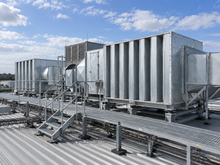
Attenuator sizing, balancing insertion loss, airflow and pressure drop
An attenuator selection sheet usually contains two numbers that people look at and one that decides whether the selection works. The two are insertion loss and pressure loss. The one is airway velocity, and it… -
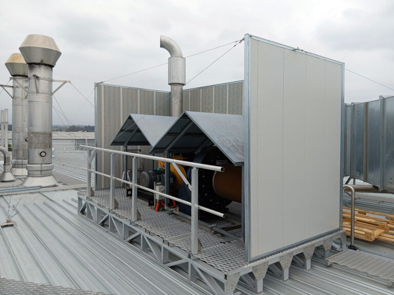
When an acoustic louvre is the right choice and when it is not
An acoustic louvre is asked to do three incompatible things through the same aperture. It has to let air through, keep water out, and attenuate sound. Each of those improves at the expense of the… -
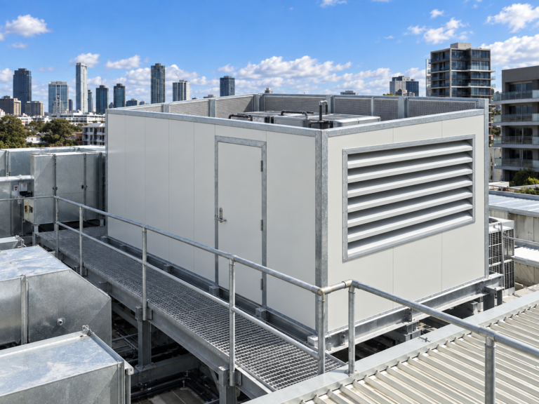
Insertion loss, transmission loss and Rw, choosing the right metric for the job
A mechanical engineer sizing a duct attenuator, an architect specifying a plantroom wall and a project manager reviewing a supplier submission can all be looking at a number followed by the letters dB and be…