
Flanking paths, why tested acoustic performance can disappear after installation
An Rw rating from laboratory testing is real, and it describes what an element achieves under the conditions it was tested in. It doesn’t automatically describe what the same panel, door or enclosure will achieve once it’s built into a project, because a laboratory test isolates one path through one element. On site, acoustic flanking…
An Rw rating from laboratory testing is real, and it describes what an element achieves under the conditions it was tested in. It doesn’t automatically describe what the same panel, door or enclosure will achieve once it’s built into a project, because a laboratory test isolates one path through one element. On site, acoustic flanking paths around the assembly are often what separates the tested figure from the measured one.
A laboratory test isolates one path
Sound transmission testing for Sonic System acoustic modular panels and Sonic Access acoustic doors is carried out to AS 1191-2002, with Rw determined to AS/NZS ISO 717.1. The specimen is mounted in an opening between two reverberant rooms, and the surrounding structure is built to suppress any path that isn’t through the specimen. The resulting Rw describes the sound reduction of that element in isolation, with flanking engineered out of the result.
That’s the correct way to test a product, and it’s also why the figure can’t be read as a guarantee of field performance. The result tells a specifier what the element can do when it’s the only path available. It says nothing about the same element installed into a wall, roof or enclosure with junctions, penetrations and adjoining structure around it.
Flanking transmission goes around the element
Flanking transmission is sound that reaches the receiver by travelling around the primary element instead of through it. The ISO 10848 series exists to measure it between adjoining spaces, which is how seriously the discipline treats it: a distinct, measurable path, separate from direct transmission through a wall, floor or ceiling. The same principle applies to industrial enclosures, acoustic walls and plant room construction. Once a primary element is in place, sound will find any lower-resistance path around it, and in a built assembly that path can matter more than the direct path through the panel or door.
Common flanking routes on industrial and construction sites include wall and roof junctions where two construction types meet; ceiling voids that run continuously above a nominally separating wall; floor penetrations; structural connections that carry vibration as well as airborne sound; door and frame interfaces; ductwork that carries noise past the point it enters a plant room; cable and pipe penetrations; shared cavities between adjoining structures; and gaps at poorly sealed interfaces between trades. None of these appear in a laboratory Rw, because the test is designed to exclude them.
Through the element and around it are separate problems
Keep the two mechanisms apart, because they’re fixed differently. Airborne transmission through the primary element depends on its mass, stiffness and construction, and that’s what the Rw describes. Flanking transmission depends on the junctions, penetrations and adjoining construction, which makes it a matter of installation and interface detailing, not of the panel or door specification. A high-Rw panel installed against a poorly sealed junction won’t deliver its rated performance, and the shortfall has nothing to do with the panel’s own transmission loss.
This matters for troubleshooting as much as for design. When an installed assembly measures below its target, the instinct is to question the product data. Often the product is performing as tested, and the gap sits in a junction, a penetration or an interface that wasn’t detailed or sealed to the same standard as the panel.
Junction detailing carries the flanking risk
Laboratory testing is the responsibility of the product supplier. Junction detailing, penetration coordination and interface sealing belong to design and construction, so the flanking risk sits with whoever coordinates the trades on site.
Take a Sonic acoustic enclosure built from panels rated to Rw 45dB, louvres assessed to Rw 33dB and single-leaf doors tested to Rw 46dB. The assembly will only approach its design performance, which the Rw 33dB louvres already cap, if the junctions between panel and louvre, panel and door, and panel and structure are detailed and sealed with the same care as the panels. An enclosure roof penetrated by unsealed conduit, or a door frame fitted with a compressed seal in place of a continuous one, opens a flanking path that no amount of panel performance can make up for.
That’s why acoustic assessments and specifications ask for junction details, penetration schedules and sealing methods alongside the Rw figures for individual products. A specification that lists product ratings without saying how those products meet at their junctions has described only part of the finished assembly’s performance.
A plant room wall with a continuous ceiling void
A plant room wall specified to a target Rw and built from a rated panel range shows the problem. If the ceiling void above it runs continuously into the adjoining space, sound travels over the top of the wall through the void however well the wall performs, because the ceiling was never part of the separating construction the wall’s Rw describes. The same applies where a services riser, cable tray or duct crosses from the noisy side to the quiet side through a shared shaft that wasn’t sealed at each level. In both cases the wall can be installed exactly as specified and still miss the intended reduction, because the flanking path was never closed.
Sequencing matters for the same reason. Acoustic panels, doors and enclosures are often installed by one trade, while the ceiling, services and structural interfaces around them are finished by others, sometimes on a different program and without a shared reference to the acoustic design intent. Where no single party is responsible for confirming that every junction around the acoustic element is sealed, flanking paths stay open simply because no trade saw closing them as part of its scope.
What specifiers and project teams should check
Reviewing a laboratory test report is a necessary step, and on its own an insufficient one. A specifier should also ask how the tested element will be integrated into the project, including which junctions, penetrations and adjoining structures will exist on site that weren’t in the test rig. The trades responsible for structure, services and acoustic fit-out need to identify and treat every flanking path before installation, not after a post-completion measurement falls short.
None of this makes laboratory testing unreliable. The result describes the tested construction under defined conditions, and the field result depends on how faithfully the surrounding construction avoids the paths the test deliberately excluded.
Close the junctions to keep the tested figure
An Rw rating from a laboratory is accurate evidence of what a product achieves under test conditions. Whether the finished installation gets close depends on the flanking paths introduced by junctions, penetrations, ductwork and interfaces, which sit outside the product test entirely. Treat junction detailing and interface sealing as part of the acoustic design, and resolve them before installation.
Related Stories
-
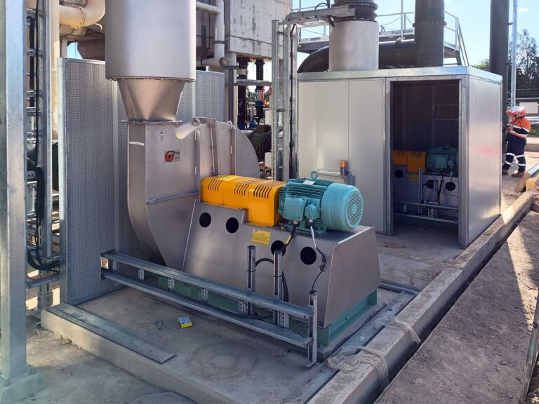
Acoustic walls and enclosures, how to decide which approach fits the plant
Whether a noisy piece of plant gets an acoustic wall or a full acoustic enclosure is often settled on budget, with the enclosure cast as the better option and the wall as the cheaper fallback…. -
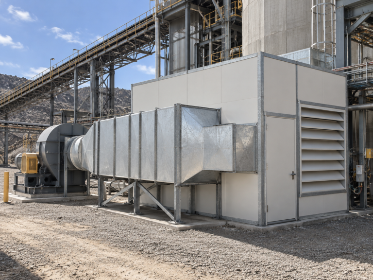
Cumulative noise, what happens when every plant item meets its individual target
A specification requires that no individual item of plant exceed 45dB(A) at the nearest receiver. Eight items are installed. Every one is measured at commissioning and every one complies. The site is measured at 54dB(A)…. -
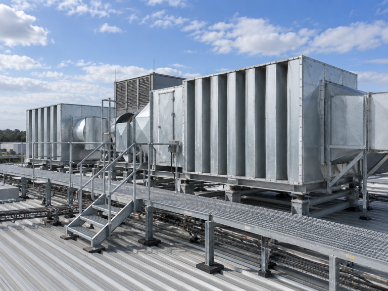
Attenuator sizing, balancing insertion loss, airflow and pressure drop
An attenuator selection sheet usually contains two numbers that people look at and one that decides whether the selection works. The two are insertion loss and pressure loss. The one is airway velocity, and it…